ELECTRONIC INTERFACING
For more detail see below.
Schematic of special interface of METEOR
Click on schematic for download the largest
image in BMP. (schema.zip 15 Ko)

 Download
experiment copper board drawing.
Download
experiment copper board drawing.
Download PCB in PDF format by Piotr !
Download PCB meteor.ci
+ components list ( 2 Ko ) for
WinCircuit 2000
available here !
The Printed Circuit Board for METEOR interfacing.

 I
I
Components face
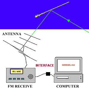
As all software, METEOR v 4.0 only cannot communicate with her environment.
He exists several methods to acquire the analogical signal ( LF of your receiver) and to transmit at the computer.
The most classic method consists in digitizing the signal with a Analogical Digital converter (ADC), for example your computer sound card.
But we preferred to create a small electronics adapted for two main reasons:
1°) For use an old machine 286, 386 or 486 (machines to the rubbish), doesn't accept all one sound card, and often again less WINDOWS. METEOR v 4.0 running under DOS.
He will be you thus easy to " dedicate " a machine to the permanent monitoring of meteor scatter !
2°) The ADC are very "noisy" for the receive !
Interferences owed to the signal of sampling and other signals GIVEN OUT by the computer are as much of drew for the one that tries to disrupt least possible a receiver.
Electronics that we use generates signals only TOWARD the computer. So 90% of interferences disappear. Remain noises owed to the map screen and the such various peripherals the hard drive, but it is sufficient to place the computer to some meters of the receiver so that manages. In the desperate cases it is necessary to move away the computer again and (or) to filter the power supply and the signal of antenna !.


1°) Assure you of the presence of a NF signal having one levels of about 500 mv crest to crest in output of your receiving FM. It is the mean level of the LINE output of a Tuner FM.
2°) plug a LF wire equipped of cinch slip on output line of your Tuner FM or your receiver and plug in Line IN of the METEOR interfacing.
3°) On the PC plug the (Cannon DB9 or 25) on the COM port available.
4°) Starting up your Tuner and your PC.
5°) Adjust your Tuner outside of all receipt of station. You must hear the characteristic noise of the FM solely.
6°) Run METEOR v 4.0
| © Pierre TERRIER 2000 | 
|